Efficient Nano‑Optical Eye Tracking
for Smart Glasses

Jipeng Sun, Lekang Yuan, Ruslan Guseinov, Bernd Bickel, Thabo Beeler, Thomas Auzinger, Felix Heide

SIGGRAPH Asia 2026

Paper Supplement BibTeX

Summary

Eye tracking is the primary input method for smart glasses, and it runs continuously on a processor that is shared with SLAM, rendering, and hand tracking. Glint-based methods transfer poorly to this form factor: frame-mounted LEDs illuminate the eye at oblique angles, so their glints are easily occluded by eyelashes, and outdoor sunlight further degrades the signal. Without glints, a rotation of the eye and a slip of the glasses can each move the pupil to nearly the same position on the sensor. In this work, we resolve this ambiguity in the optics rather than in the network, by jointly optimizing a nanophotonic metasurface, the sensor pixel pitch, and the network for both accuracy and computational cost. Our method achieves a 3D gaze error of 0.75° at 480 MMACs, an accuracy comparable to that of De2Gaze at 14× less compute. We evaluated a fabricated prototype with 20 subjects, using motorized stages to emulate slippage. Under axial slippage, its gaze error is 1.17°, compared with 2.02° for a hyperbolic lens.

Real-Time Eye Tracking

On the benchtop rig, a subject plays a whack-a-mole game with the fabricated prototype, using gaze as the only input. Without glints, the system estimates the gaze point on the screen from each raw camera frame, and the mallet moves to that point. Partway through the sequence, the X and Z stages translate the camera, as indicated by the arrows in the insets, while the score keeps increasing. The system is not retrained or recalibrated after the camera moves, either for this subject or for the two subjects who follow.

The Slippage–Rotation Ambiguity

Glasses slippage and eye rotation can produce nearly identical eye-camera images. In the rendered example above, an eye rotation of about 6° and a 1.2 mm slip along the nose each place the pupil at the same position in the image of the frame-mounted camera; the ring marks this position. The animation alternates between the two states: the scene changes, but the camera image stays the same. The true gaze directions nevertheless differ, as the two gaze rays at the end of the loop show. A conventional lens provides no cue that separates the two motions, and the illumination that glint-based trackers require is difficult to integrate into compact eyewear. The information needed to resolve this ambiguity must therefore be encoded in the measurement itself.

Co-Designing the Optics, Sensor, and Network

By designing the lens, the sensor, and the network as a single system, we optically encode the cue that separates rotation from slippage. The three stages of an eye tracker are conventionally designed in isolation: lenses are optimized for sharpness and discard depth cues, sensors are optimized for high pixel count, and the network is left to resolve ambiguities that the optics could have removed physically. Instead, we optimize all three stages under a single objective that accounts for both task error and computational cost. An evolutionary outer loop samples subnetworks from a weight-sharing supernet under a compute budget. For each sampled subnetwork, an inner loop jointly fine-tunes the metasurface phase, the pixel pitch, and the subnetwork itself.

One objective for optics, sensor, and network. The objective combines an optics loss that pushes the sensitivity fields of eye rotation and slippage apart, a compute loss on the pixel pitch and the active subnetwork, and a task loss on pupil segmentation and slippage estimation.

Optimized with this bi-level search, the metasurface maps eye rotation and glasses slippage to visibly different sensor patterns, with 1.6× the separability of a hyperbolic lens and 1.8× that of a double-helix lens. The two motions are therefore separated optically, before digitization. The forward model is differentiable end to end, from the nanopillar diameters to the noisy sensor image. A single elastic MobileNetV3 backbone has two heads, one for pupil segmentation and one for 3D displacement regression. A spherical-eye solver combines their outputs into a gaze direction.

Trained on Rendered Eyes, Tested on Real Ones

Because no real-world dataset provides ground truth for both gaze and sensor displacement across a diverse population, we train on rendered data. The training images are path-traced from parametric face and eye models. For each frame, we sample a random subject and a 6-DoF state that combines eye rotation with slippage along the nasal bridge. To collect real data, we imaged 20 subjects through the fabricated optics on the benchtop rig, with motorized stages setting seven slippage states. Across 8,219 evaluated frames of these captures, the predicted pupil contours reach an intersection over union of 0.94 with the ground truth. In the montage below, the upper two rows show rendered training images. The lower two rows show real prototype captures, each with the predicted pupil contour in red overlaid on the ground-truth contour in green.

Experimental Evaluation

Using two-step electron-beam lithography, we fabricated the co-optimized metasurface and a hyperbolic baseline on the same material stack: a 0.5 mm fused-silica substrate coated with 700 nm of amorphous silicon. A 1 mm circular chromium aperture was patterned first, followed by a nanopillar array etched with a pseudo-Bosch process. Because both optics share this stack and process, they differ only in their phase profiles.

The rig reproduces the geometry of a near-eye display. Each subject sits with their head on a headrest and fixates each stimulus in a 7×7 grid spanning 25°×35° on a monitor, while a near-infrared source illuminates the eye. The prototype is mounted about 2 cm below the eye, and two motion stages translate it through seven slippage states: the origin, two lateral shifts along dx, and four axial shifts along dz, in 2.5 mm increments. This protocol yields 343 samples per prototype for each of the 20 subjects.
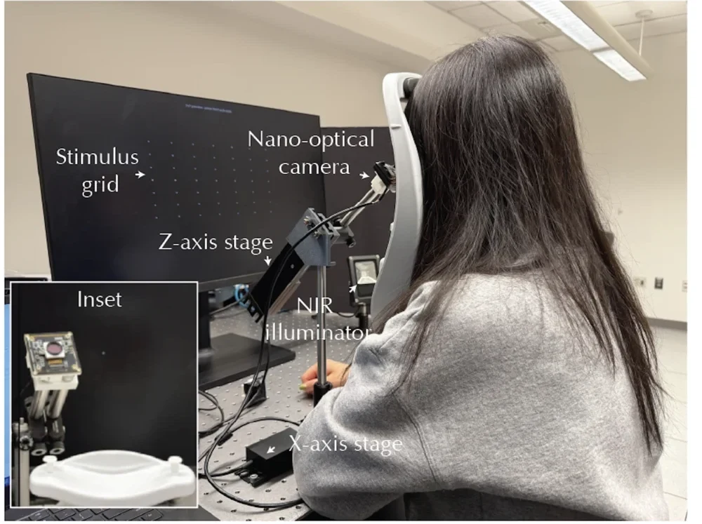
Photograph of the benchtop capture rig. A seated subject with their head on a headrest faces a monitor that displays the stimulus grid. Labels mark the stimulus grid, the nano-optical camera in front of the eye, the Z-axis stage, the NIR illuminator, and the X-axis stage on the optical table. An inset at the lower left shows the assembled nano-optical camera on its mount.
Benchtop capture rig. Inset: the assembled nano-optical camera.

Each target in the figure has two markers whose sizes indicate the errors: blue for the hyperbolic baseline and orange for our design. Across the 20 subjects, our design predicts slippage with a mean absolute error of 0.52 mm, compared with 0.95 mm for the hyperbolic baseline on the same rig. This indicates that the depth cue comes from the learned optical encoding rather than from the network. A small regressor maps the pupil parameters and the estimated slippage vector to a screen position. Under axial slippage, our design achieves a mean gaze error of 1.17°, compared with 2.02° for the baseline. Under lateral slippage, its error is also lower: 1.26° compared with 1.49°.

BibTeX

@inproceedings{sun2026nanoeyetracking,
  title     = {Efficient Nano-Optical Eye Tracking for Smart Glasses},
  author    = {Sun, Jipeng and Yuan, Lekang and Guseinov, Ruslan and Bickel, Bernd
               and Beeler, Thabo and Auzinger, Thomas and Heide, Felix},
  booktitle = {SIGGRAPH Asia 2026 Conference Papers},
  year      = {2026},
  publisher = {Association for Computing Machinery}
}